Creating My First Badge
So, the 2024 Palmetto Cyber Defense Competition has concluded and the VoIP setup I worked on all last year worked perfectly. No real issues, all of the contingencies had been planned for…it was very nice. The competitors and volunteers found some great uses for the phones and I was pretty proud.
However, it’s time to prepare for the 2025 competition.
The new plan: make a cool Red Team badge.
This is something I’d been thinking about since DEFCON 26 and I purchased my first badge. I have experience in PCB design, working with microcontrollers, turning on LEDs, and basic electronics. However, the idea to even start something like this was very intimidating.
Fast forward to this year and I’ve gotten better with my designs and electronics knowledge. There were conversations from our Red Team members that usually centered around things like “wouldn’t it be cool if we had badges” and “we should do badges” and…
…you get the point.
The Plan
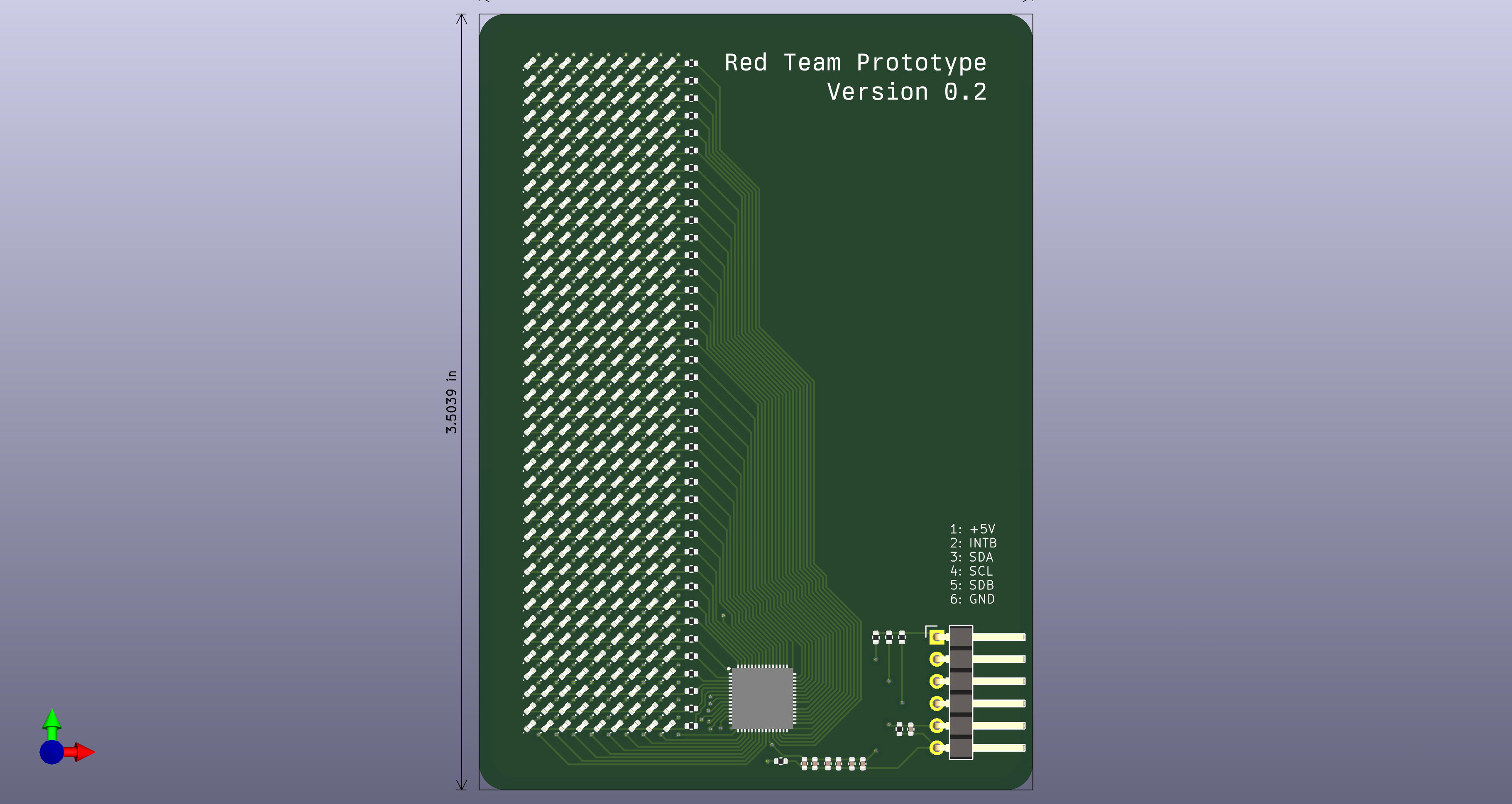
So, after cleaning up post competition it was time for a new project. It had been a bit, and with all that talk I figured it was now time to try this out. Figured a badge about the size of a Magic: the Gathering card (about 2.5” by 3.5”) with a “massive” LED matrix on one side and some cool artwork on the other side of the front of the badge. Seemed like an easy enough idea to aim for, and you can throw a rock and hit some nice LED matrix ICs.
Right now, the plan is pretty straightforward:
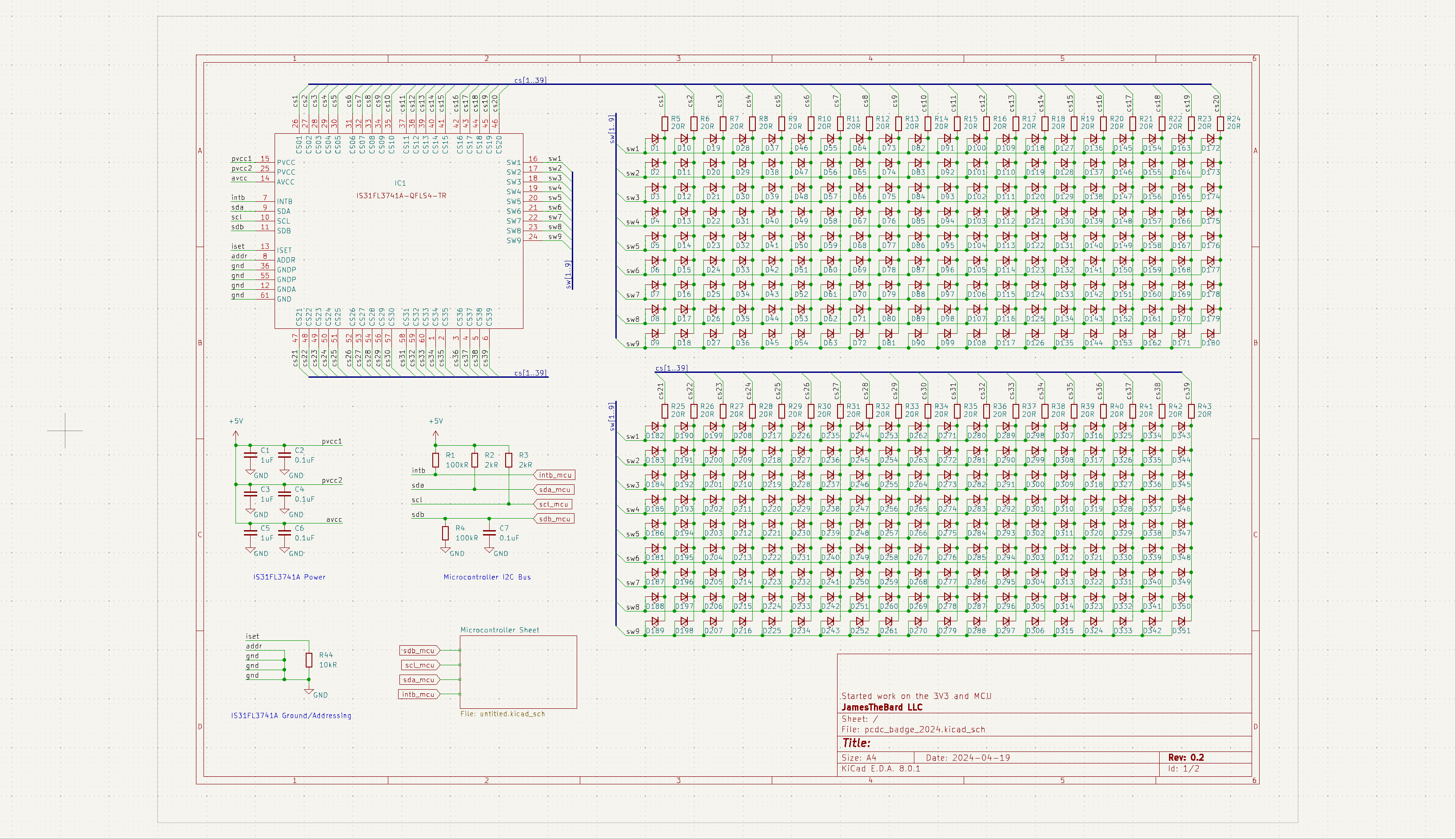
- Use the Lumissil IS31FL3741A LED matric IC. This will give me a 9x39 matrix with some crazy controls on what the LEDs do via I2C. Fairly inexpensive at ~$2.50 for what it does.
- Fit that matrix on the badge. This is gonna require 351 LEDs and I need to fit them in a pretty small space. So, going with a size of 0402 which is 1.0mm x 0.5mm in size (1005). Also, I will 100% be getting a stencil for this project as I’m very, very sure I can’t hand solder something that tiny.
- Incorporate a microcontroller to push info to the LED matrix. I’m going to try and use an Atmel ATMEGA328P which should be perfect. I’m also going to run the unused pins to the edge of the badge along with providing an easy way to program it like an Arduino. I like the idea of people hacking on this thing.
- A few buttons so you can control what’s being displayed on the badge.
- USB connector for charging/power/uploading new stuff to the badge and a decent battery to power it.
This is going to take me a long while, but I’m giving myself a long time to get this done. If everything works out, I’ll toss this to JLCPCB and have them do the assembly because no one wants to solder 351 0402 LEDs.
Current Progress
- Implemented the IS31FL3741A LED matrix1
- Laid out the resulting schematic1
- Ordered the prototype PCBs from JLCPCB2
- Ordered 10x IS31FL3741A ICs from Mouser
- Ordered the capacitors, LEDs (amber)3, resistors from LCSC
- Ordered a few Atmel ATMEGA328s and associated programmers
Footnotes
I either need to get far better at scripting in KiCad, or there’s evidently just pain in laying out all those LEDs. Lots of copy-pasting. Then you get to manually lay all of those out on the PCB. There’s definitely an easier way, but it’s done now and I will never stop complaining about the pain. ↩ ↩2
Went with a 4-layer board, nothing too fancy. Also, very, very inexpensive. ↩
Had to order them from LCSC because I need a lot of them and they are far, far cheaper from LCSC. ↩

